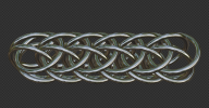
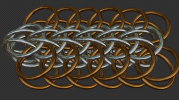
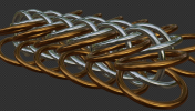
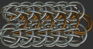
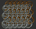
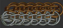
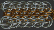
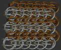
Tethered Full Persian 6-in-1 (Grizzly)

Alton H

Established Member
Active Member
New Member
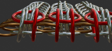
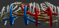
Hey guys! It has been a really long while since I've posted something, and I would post pictures, but obviously I cannot. I stumbled upon this while trying to mess around with Full P6-1, as one does I suppose. Anyway, I found that if you insert a tether between the rings "protruding" on the top section of the picture, and shown "flat" on the bottom, you can link multiple of these chains together. Depending on your aspect ratio, you can do this on both faces. What results is a very nice sheet that is fairly thick and looks very nice. It curls more on one end than the other if you only tether one side. I would like to call the band created by four tethers on each unit by the name, "firecracker", as that's just something it reminds me of. It is possible to tether these chains together in several ways. But doing so in the way I described is the most orderly as the tethers do not jangle around. The sheet produced looks something like dragon scale. Assuming you only tether it on one face, you end up with what looks like scales on one face, and a twill weave on the other. It looks so very nice, and is so very nice to handle. By virtue of the protruding rings, that are sort of perpendicular to the plane of the sheet, it rolls fairly smoothly in a certain direction.

The sheet produced, I would propose to be named, "Tethered Full Persian 6-in-1 (Grizzly)". But as this is *really* wordy, I would also propose an alternate name, Grizzly scale. There are multiple ways to tether this sheet however. Assuming you only tether one face, it could be considered "half" in some regard, but I think the fractions involved in Persian weaves make that terminology confusing. You could also alternate the face on which you tether the chains, which reminds me of a box pleat. I wouldn't call it that either because it kind of sounds like "box chain", which it is not.
I don't know if this should be a new post entirely, and I'm sorry for the long post here in the discussion section.
The ring specifications I use to make this were 20awg, half-hard, red brass, round wire, wound around a 6mm steel rod. The spring back was not enough to allow the rings to fit around a 7 mm rod.
When single-sidedly tethered, the sheet is fairly loose at a small size, but experiences greater lock up as the chains are lengthened. I noticed this because I was able to create a cylinder, but as I unwrapped, lengthened, and then tried to re-wrap the sheet back into a cylinder, I found I needed to add more columns of FP6-1 (grizzly) chain.
Doing a full four tether rings on each unit at the end of a chain makes a very nice termination to the chain. This is what I would like to call the "firecracker" band.
I'm a little bit more busy recently, but I'll be happy to answer any questions anyone has. I might take a while to respond though.
 

chainmaillers.com

Administrator
Staff member
Hey guys! It has been a really long while since I've posted something, and I would post pictures, but obviously I cannot.
Welcome back :) For someone who it's not obvious to, can you say why you can't post pictures?

Anyway, I found that if you insert a tether between the rings "protruding" on the top section of the picture, and shown "flat" on the bottom, you can link multiple of these chains together.
Either of the mirror pair lean rings can be either protruding or flat depending on the orientation of the chain. I'm not quite understanding how you are tethering the chains together? Are you doing something like this picture from chainmailbasket.com (with a grizzly version of FP6-1 of course)?

full_persian_6in1_sheet_standard_54_31.jpg


Do you have a Measured AR (not Mandrel AR) for the ring size you used?
 

Alton H

Established Member
Active Member
New Member
Welcome back :) For someone who it's not obvious to, can you say why you can't post pictures?


Either of the mirror pair lean rings can be either protruding or flat depending on the orientation of the chain. I'm not quite understanding how you are tethering the chains together? Are you doing something like this picture from chainmailbasket.com (with a grizzly version of FP6-1 of course)?

full_persian_6in1_sheet_standard_54_31.jpg


Do you have a Measured AR (not Mandrel AR) for the ring size you used?
I thought I didn't have the ability to post pictures because I'm below the three post rolling threshold, but I might have been misremembering. The tethers I use are on the other faces of the chain, 90° offset from what is shown in the picture from chainmail basket. Measuring the wire diameter I use to make the Rings, I get arrange of .77mm to .81mm, though most of the rings fall within a thickness of .79mm-.80mm. The inner diameter I use is a bit more variant, but it rests around 6.4mm to 6.5mm the tethers that can be used are either that, or as I did with the band, what varies between 5.34 mm and 5.50 mm. These are all using the same diameter of wire. I have more recently got him a manual winding setup that should allow my ring sizes to take on a more precise standard than before.
(I'm using the mobile app so I'll upload some pictures from my computer)
 

Alton H

Established Member
Active Member
New Member
470050635_1031033465498130_8887244122136039807_n.jpg

Top image: clockwise from bottom left: "cylinder" with tethers on inside face, "firecracker" band with extended grizzly chain, a single grizzly chain with all possible "tethers" added.

467469306_1976850186149849_2821561271931482960_n.jpg

Second image: inner face of the "cylinder" shown above, unfurled and laid out in sideways tension.

467463591_1123936135331986_6424184022797900712_n.jpg

Third image: same as second, but "squished" to take up less space, as a closer packing-- not in tension.

462583415_2013169625852817_866228193134038903_n.jpg

Fourth image: unwrapped "cylinder" with tethered face down, laid out in sideways tension.

462568235_1275519157108780_1514653593135010011_n.jpg

Fifth image: same as fourth, but not in tension, "squished" as in the third image.
467468825_1410871923690395_1736434617689315368_n.jpg

Fifth image: the same "firecracker" band, with a single layer of tinned copper to show the contrast for "tether" placement.
 

Alton H

Established Member
Active Member
New Member
as a short update: the band, when made using only the ~6mm 20ga rings (rightmost in the first image I posted), is resistant to twists, bends nicely like a ribbon but with significantly higher bend radius (less freedom), but most interestingly, when you swivel the band within the plane, it returns back to straight. It is somewhat elastic.
I wouldn't say this is a bug, as the elastic deformation that occurs on each ring appears to be similar to that of a coil-type spring, but obviously this will depend on the metal used as well as whether the rings are sealed with solder, a rivet, or welding. I imagine this behaviour is unique to butted maille, but that is merely intuition.
 

chainmaillers.com

Administrator
Staff member
The inner diameter I use is a bit more variant, but it rests around 6.4mm to 6.5mm
Is this the mandrel diameter or did you measure the ID of the actual rings after coiling and cutting?

Let me see if I have this straight :) The following renders are done with AR of 8.0

You take Full Persian 6 in 1 (Grizzly).
1735676092073.png

You make a band out of it by adding the following rings. Each copper ring going through a single stainless ring?
1735676404632.png
another angle:
1735676500335.png
You should also be able to make a band like the following:
1735676751749.png
which would make the sheet form this:
1735677910130.png

Do I have that all correct?

Technically, you should also be able to do something like this:
1735678167853.png
or this:
1735678273377.png
or a sheet like this:
1735678400330.png


I should also ask if in your tube form (what you called a cylinder version), are there only single copper lean grains (as opposed to a mirror grains) to allow the rotation to connect it to itself?
 
Last edited:

Alton H

Established Member
Active Member
New Member
Is this the mandrel diameter or did you measure the ID of the actual rings after coiling and cutting?
I used electronic calipers to measure the inner diameter and the wire diameter. Going forward, I'll try to remember to specify mandrel or measured by calipers :)


Technically, you should also be able to do something like this:
1735678167853.png
That is super cool! I love that!
You make a band out of it by adding the following rings. Each copper ring going through a single stainless ring?
1735676404632.png
another angle:
1735676500335.png
You should also be able to make a band like the following:
1735676751749.png
which would make the sheet form this:
1735677910130.png

Do I have that all correct?
Yes! All of this is correct. I'm a little embarrassed to not have seen the possible version you pointed out, but excited nonetheless. I use brass, bronze, and tin plated copper.


I should also ask if in your tube form (what you called a cylinder version), are there only single copper lean grains (as opposed to a mirror grains) to allow the rotation to connect it to itself?
Yes, there is only one set of lean grains. I will say that I've toyed with the idea of alternating which lean grains are added as one proceeds from column to column, something like a box pleat. This should allow curvature in both directions.
 

chainmaillers.com

Administrator
Staff member
Yes, there is only one set of lean grains. I will say that I've toyed with the idea of alternating which lean grains are added as one proceeds from column to column, something like a box pleat. This should allow curvature in both directions.
Depends what you mean by "curvature". If you are talking about making a tube in either direction, I would say no. (Just like I would say your current tube (cylinder) can only be made in one direction.) The "tethers" would need to be increased in size to make an "inward" tube to allow for enough space. If you tried to tube upward, the red rings would not allow for enough curvature (unless there was a huge sheet) while downward would not cause collisions in the same way.
1735782093509.png
Even with pleating, you would still run into the same problem, the portion of the FPG chains that protrudes from where the tethers are would collide. Those collisions would make a tube problematic in either direction (I think).
1735782640735.png
 

Alton H

Established Member
Active Member
New Member
Depends what you mean by "curvature". If you are talking about making a tube in either direction, I would say no. (Just like I would say your current tube (cylinder) can only be made in one direction.) The "tethers" would need to be increased in size to make an "inward" tube to allow for enough space. If you tried to tube upward, the red rings would not allow for enough curvature (unless there was a huge sheet) while downward would not cause collisions in the same way.
View attachment 9097
Even with pleating, you would still run into the same problem, the portion of the FPG chains that protrudes from where the tethers are would collide. Those collisions would make a tube problematic in either direction (I think).
View attachment 9098
I will say that in order to make the tube with simply one face of tethers, you need more columns than you'd initially estimate based on the flexibility of the sheet..if the columns aren't sufficiently long, the tube *can* be made with as few as six columns. But as you lengthen the columns, the sheet locks up more.
I definitely didn't think about the diagonal pinning you pointed out here. I might experiment and get back to you on it. Currently I'm waiting on a shipment of wire. Happy New Year!
 

Alton H

Established Member
Active Member
New Member
Advertisement
I started whipping this up, and I must say that it is very difficult to get the hang of. I wanted to give my impression immediately after I started making some actual progress so that I don't have a biased impression of it after I'm done with it. In the image you have created, I will refer to left and right. When making it, I have found that the easiest way to fix any mistake is to just take apart the weave at the place where the mistake occurs and use the rings to the "right" of it as father to continue the pattern "leftwards". It is very difficult to propagate to the sheet "rightwards". At a length of five rings, there is very minimal curvature "up and down", and a little bit of curvature "left and right". Frankly, I would rather describe curvature in terms of pitch, yaw, and roll, (airplane terms) as they are fairly precise. I would say that there is some pitch, minimal roll, and not enough length to observe yaw conclusively. That is, assuming that the "left" or "right" of the image are the front and back of the "airplane." I will take a few pictures throughout the process and then upload them via computer later.
 

Alton H

Established Member
Active Member
New Member
I started whipping this up, and I must say that it is very difficult to get the hang of. I wanted to give my impression immediately after I started making some actual progress so that I don't have a biased impression of it after I'm done with it. In the image you have created, I will refer to left and right. When making it, I have found that the easiest way to fix any mistake is to just take apart the weave at the place where the mistake occurs and use the rings to the "right" of it as father to continue the pattern "leftwards". It is very difficult to propagate to the sheet "rightwards". At a length of five rings, there is very minimal curvature "up and down", and a little bit of curvature "left and right". Frankly, I would rather describe curvature in terms of pitch, yaw, and roll, (airplane terms) as they are fairly precise. I would say that there is some pitch, minimal roll, and not enough length to observe yaw conclusively. That is, assuming that the "left" or "right" of the image are the front and back of the "airplane." I will take a few pictures throughout the process and then upload them via computer later.
At 7 units in length, the curvature in Pitch has become more apparent. The yaw has become more apparent, though still noticeably restricted if anything, the role has become less noticeable. Perhaps even negligible. I will start expanding it sideways if I can. I do not think that it is possible to stitch two bands together.
 

Alton H

Established Member
Active Member
New Member
At 7 units in length, the curvature in Pitch has become more apparent. The yaw has become more apparent, though still noticeably restricted if anything, the role has become less noticeable. Perhaps even negligible. I will start expanding it sideways if I can. I do not think that it is possible to stitch two bands together.
Expanding it sideways is annoying. It is just simply awful. However, this is due to the process requiring you to bend a ring open, slide it, partially close it, slide it, open it more, close it whatever, slipping it between other rings and then modifying how the opening in the working ring is. That is what makes it so annoying. But I've found that this tedium can be avoided by putting in the minimum number of lean grains to entirely cover the "rolly" rings (I will explain what I mean in a moment) , meaning just four lean grains per pair of "rolly" rings.
When you hold the piece in your hand, it rolls very nicely from front to back, as the rings that protrude out of the surface of the sheet act as bearings. These are what I'm going to refer to as "rolly" rings. If there is a better term, please let me know.
When expanding sideways with excess lean grains, it is easier to expand in the direction the rings diverge.

Again, going back to this image, that means expanding "rightwards"

After a little bit of experimentation, I have determined for myself that adding rings on with only the minimum lean grains required is no more or less difficult going leftwards or rightwards then going the other direction. So that is nice. At some point, I may revisit this, seeing whether it is possible to expand a short into another piece of long band, but not right now.


Looking at the sheet now, after expanding a couple rows out, I feel that the texture of the weave resembles a scallop shell or the denticles of a shark under a microscope.
 

Alton H

Established Member
Active Member
New Member
Okay so after I've played with it a bit I can say that unexpectedly, what I have called a "pitch" curve actually creates a bowl shape because it forces a corresponding "roll" curve. That is, the concavity is in the same direction. Which I suppose makes sense, but it's interesting that it forces that concavity. It is possible that I did something wrong, but I do not believe so. They suggests to me that over a larger scale, this sheet would remain flat, as the curve outpaces the wiggle room. Either that, or the wideness of the band has a greater effect on the curvature, The wider the band already is. I hope to someday be able to experiment with that, but this has already taken something like 4 hours to produce a physical piece.
 

Alton H

Established Member
Active Member
New Member
IMG_20250101_194910162.jpg

IMG_20250101_202730182.jpg

IMG_20250101_204203562.jpg

IMG_20250101_205005678.jpg

Images! These are made of "silver" copper from Wal★Mart. Sorry for the messy background
 

Alton H

Established Member
Active Member
New Member
It definitely works!
The muscle memory for expanding the sheet Is completely different from extending it. As I suspected, curving it one way forces the hexagon to take on a bowl shape. Over a larger area, the overall radius of curvature gets larger, seeming to accelerate compared with the size of the sheet.

IMG_20250103_205000663.jpg
 

chainmaillers.com

Administrator
Staff member
It definitely works!
The muscle memory for expanding the sheet Is completely different from extending it. As I suspected, curving it one way forces the hexagon to take on a bowl shape. Over a larger area, the overall radius of curvature gets larger, seeming to accelerate compared with the size of the sheet.

View attachment 9146
That's nice to see. The curvature could probably be reduced by increasing the AR a tiny bit. This version would be an offset fp grizzly sheet. :D Do you have a measured AR for the rings that you used?
 

Alton H

Established Member
Active Member
New Member
That's nice to see. The curvature could probably be reduced by increasing the AR a tiny bit. This version would be an offset fp grizzly sheet. :D Do you have a measured AR for the rings that you used?
I do not have a measured aspect ratio for these rings. I coiled them on the same 6 mm rod, and one thing that I will note is that there is significantly less springback. As I expand the sheet more and more, the radius of curvature gets larger and larger. As I expected, the overall curvature tends to flatten. My "silver" copper rings are just barely over 6 mm, whereas my bronze and brass rings have a fairly sizable springback. I feel that it is perhaps conceivable that a perfect 6 mm would not allow for the sheet weave. But the observed accumulated wiggle room seems to be on the order of like, Maybe 0.2%? What I mean by this is I can put the hexagon on the measuring lines you see on my mat, and over a length of 4 cm, I observe a possible stretch of about 1 mm. There is very little wiggle room. I have added in an outline of red brass, though I believe this outline should account for a fairly negligible change. My rings are not perfectly circular and the difference is likely within the margin of error over a large sheet.
 
Top